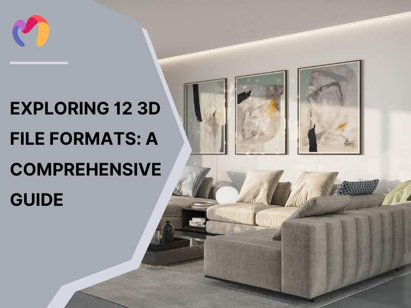
Exploring 12 3D file formats: A comprehensive guide
Update: 29/10/2025
3D file formats are digital standards that store details about three-dimensional objects, including their shape, textures, and animations, and the right choice can prevent problems such as low-quality prints, software conflicts, or heavy files that slow projects down. This guide reviews 12 widely used formats and explains their specifications, strengths, and professional uses, helping designers and architects pick the ones that fit their needs.
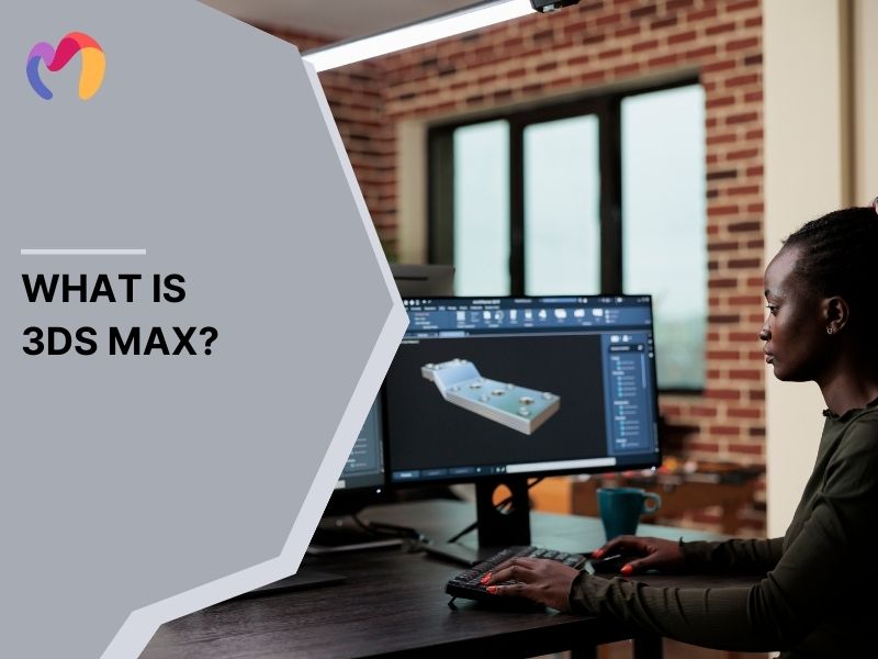
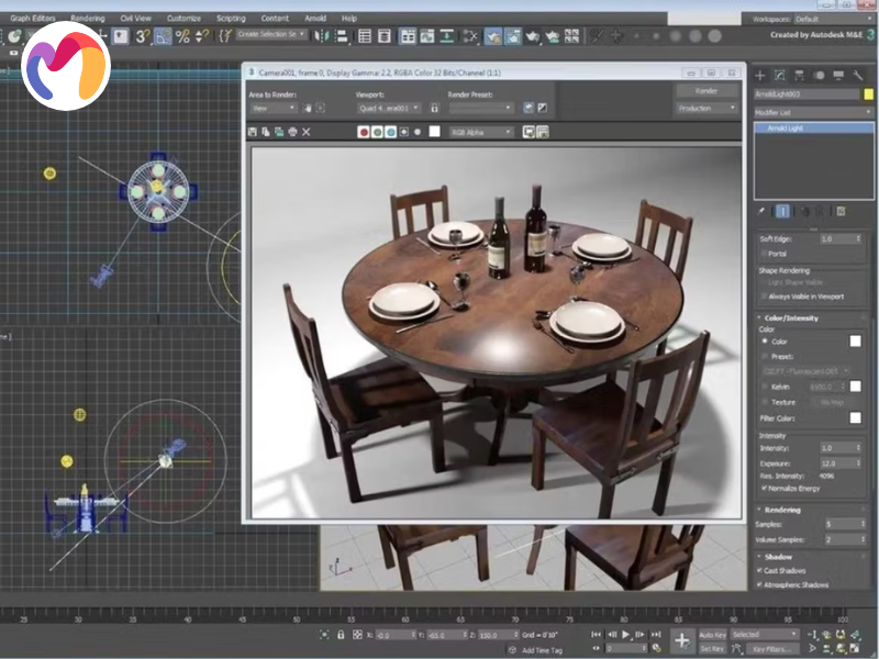
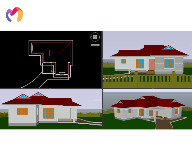
1. 3DS MAX
Autodesk’s 3DS MAX format supports architectural visualization, interior and exterior design, game development and film production. Originating from 3D Studio in 1990, it became an industry standard by the early 2000s. Design studios and architects use it to create detailed models of buildings, interiors and cinematic environments.
The format represents geometry through polygon meshes, splines and NURBS surfaces, giving designers parametric control over complex forms. There are three main advantages of this format to highlight:
- Highly detailed and realistic renders: Models deliver lifelike visualization that enhances client presentations.
- Great for large-scale projects: Complex buildings and environments are supported without losing structural precision.
- Extensive community and resources: Users benefit from tutorials, plugins and libraries that accelerate workflow.
Files save as native .MAX documents that hold full scene data—geometry, materials, lights—and they also export to formats like FBX and OBJ. Because high-polygon models and detailed textures can make.MAX files very large, professionals often optimize by simplifying geometry and cleaning materials to keep projects efficient.
2. FBX
The FBX format is a file standard created for exchanging 3D content between design and animation software. First developed by Kaydara in 1996 and later acquired by Autodesk in 2006, it has become widely used in architectural visualization, interior design and game development. Designers and visualization specialists depend on it to move detailed building models and scenes across platforms like Maya, 3ds Max, Unity and Unreal Engine.
FBX stores data through polygonal meshes as the main geometric method, while also supporting hierarchical structures and animation rigs for dynamic presentations. There are three main advantages to note:
- Widely accepted across industries: The format ensures compatibility with major 3D modeling, animation and game engines.
- Preserves data integrity when transferring between programs: Files retain geometry, textures and animation without major losses.
- Excellent for collaborative projects: Teams can share assets seamlessly across different software environments.
3. OBJ
The OBJ format is a 3D file standard created by Wavefront Technologies in the 1980s for their Advanced Visualizer software and it became a universal method for sharing static 3D models. It gained strong adoption in architecture, interior design and exterior visualization, as well as in 3D printing, where it supports model fabrication and design prototyping across different platforms.
OBJ stores geometry through polygonal meshes, recording vertices, normals, texture coordinates and faces defined by triangles or quadrilaterals. It also supports free-form curves and NURBS surfaces, which help capture curved facades and organic interior features. There are three main advantages of this file format to highlight:
- Simple and lightweight: The format uses straightforward text-based definitions that make it easy to parse.
- Universally supported across many 3D applications: Designers can open OBJ files in nearly every modeling, rendering, or printing tool.
- Easy to edit and convert to other formats: Its ASCII structure allows direct editing and smooth conversion workflows.
4. STL
The STL format is a 3D file type created in 1987 by Chuck Hull for stereolithography and it soon became the standard for 3D printing and rapid prototyping. Its simplicity and cross-platform support made it popular among architectural model makers and product designers, who use it to turn digital designs into physical prototypes.
STL represents surfaces using a triangular tessellation, where each face is built from three vertices and a normal vector in 3D space. This approach converts curved geometry into faceted surfaces that manufacturing systems can process.
This method offers two key advantages:
- Simple to use and widely supported by 3D printers: The format provides a straightforward geometric structure that printing systems can easily interpret.
- Ensures compatibility with most 3D printing systems: Its universal adoption allows seamless transfer of designs across different machines and platforms.
5. Collada
The Collada format is a 3D interchange standard created by Sony Computer Entertainment in the early 2000s to move complex assets between modeling tools and rendering engines. It is now managed by the Khronos Group, certified under ISO/PAS 17506 and widely used in gaming, film production, architecture and engineering. Designers and engineers adopt Collada for building information modeling (BIM), virtual simulation and seamless collaboration across platforms.
Collada uses an XML-based schema that organizes polygon meshes, scene hierarchies, animation data and material details inside .dae files. This structure works for both static architectural models and animated sequences, while keeping files human-readable for editing.
This geometric representation method brings three notable advantages:
- Cross-Platform Compatibility: Collada files enable seamless transfer of 3D assets between diverse software platforms without vendor lock-in.
- Comprehensive Feature Support: The format preserves textures, animations, lighting and physics data, making it suitable for complex interactive or visual projects.
- Open and Extensible XML-Based Format: Its XML foundation ensures readability and customization while promoting interoperability across industries.
6. IGES
The IGES format is a neutral CAD standard created in the late 1970s by the US Air Force, NIST and industry leaders such as Boeing to solve compatibility issues between design systems. By 1980, it became an ANSI standard and it has since been used widely in aerospace, automotive, defense and architecture. Engineers and architects rely on IGES to transfer precise 2D drawings and 3D models across platforms, making it a trusted tool for collaborative design and manufacturing.
IGES represents geometry through wireframes, freeform curves, boundary models and constructive solid geometry, stored as ASCII text records with mathematical accuracy. his geometric representation method brings two clear advantages:
- Preserves Dimensional Accuracy: The format captures precise geometric definitions, ensuring fidelity in engineering and manufacturing processes.
- Widely Supported in Engineering and Manufacturing Fields: Its long history and neutrality make it a common exchange format across CAD software, enabling smooth interoperability.
7. STEP
The STEP format is a standardized CAD exchange model created by ISO in the late 1980s and released as ISO 10303 in 1994 to solve compatibility issues between proprietary design systems. It allows engineers to share detailed 3D data—including geometry, assemblies and technical metadata—across platforms in industries such as aerospace, automotive and precision manufacturing. Companies use it for collaborative design, engineering analysis and long-term storage of technical documentation.
This geometric representation method offers two major advantages:
- Preserves Complete Data Integrity: The format retains not only geometry but also assemblies, relationships and metadata, ensuring accurate technical communication.
- Excellent for Complex, Multi-Disciplinary Projects: Its structured schema supports collaboration across diverse engineering fields, enabling smooth integration of mechanical, electrical and architectural components.
8. VRML/X3D
The VRML and X3D formats are standards for web-based 3D visualization. VRML was introduced in 1995 and gained ISO recognition in 1997, while X3D expanded its scope in the early 2000s with an XML-based structure and richer features. These formats support interactive objects and immersive environments, which are widely used in multimedia projects, scientific research, education and architectural presentations. Designers, educators and researchers rely on VRML and X3D to create virtual environments, share educational models and deliver 3D content across the web.
Both formats use hierarchical scene graphs that organize polygonal geometry, parametric surfaces, animation frameworks, lighting and scripting for interactive user experiences. X3D extends this with shader technologies, geographic data and metadata systems that help manage large-scale architectural or scientific projects.
This geometric representation format offers three clear advantages:
- Browser-Based 3D Environments: The formats enable interactive 3D scenes to run directly in standard web browsers without specialized software.
- Supports Real-Time Collaboration: Shared online spaces allow multiple users to interact within the same 3D environment simultaneously.
- Cross-Platform Support: Their open standards ensure compatibility across operating systems, devices and network infrastructures.
9. AMF
The AMF format (Additive Manufacturing File) was created by ASTM International in 2011 to overcome the limits of the older STL format. It became an ISO 52915 standard in 2013, with new features added in version 1.2 released in 2020. Built on an XML-based structure, AMF supports advanced 3D printing workflows with capabilities such as color details, multiple material definitions and internal lattice structures. Industries like medical device design, aerospace engineering and architectural modeling use AMF for high-precision and customizable fabrication.
AMF uses curved triangular tessellation, which models smooth surfaces with fewer polygons than STL, while still carrying data about color, texture and material properties. AMF files provides two major advantages:
- More detailed and accurate than stl for 3D printing: AMF geometry captures curved surfaces more faithfully, producing higher-quality prints.
- Supports full-color models and intricate design elements: The format preserves complex visual and structural details, enabling richer fabrication outcomes.
10. 3MF
The 3MF format (3D Manufacturing Format) was created by the 3MF Consortium in 2015, led by Microsoft and other industry partners, to overcome the limits of STL and AMF while improving cross-platform 3D printing compatibility. It allows full model storage, including geometry, materials, color details and print settings, which makes it highly useful for CAD programs, slicing tools and manufacturing systems that need accurate design simulation and direct printer support.
3MF uses a triangular mesh structure that carries color, texture, material properties and slicing instructions through a zipped XML framework. This 3D file format delivers two main advantages:
- Efficient and Accurate for Manufacturing: 3MF geometry enables precise translation from design to print, supporting high-quality fabrication.
- Supports Full Model Data in One File: The format consolidates geometry, materials, colors and settings, ensuring a complete and portable design package.

11. USD/USDZ
The USD format (Universal Scene Description) was created by Pixar as a standard for managing complex 3D scenes and was open-sourced in 2016 to support collaborative editing across digital pipelines. Apple introduced USDZ as a lightweight archive version tuned for augmented reality (AR) and the format gained wide adoption through the Alliance for OpenUSD. Both USD and USDZ are widely used in film production, architectural visualization and digital applications where consistent asset management and smooth integration are required.
USD supports polygonal meshes, NURBS surfaces and hierarchical scene graphs as its geometric core, enabling advanced shading systems and physically based rendering workflows. This geometric representation method provides two main advantages:
- Efficient Scene Management and Real-Time Rendering: The hierarchical scene graph organizes assets for scalable, high-performance visualization.
- Emerging as a Future Standard for Interactive Design Visualization: Broad industry support positions USD as the backbone for collaborative and immersive workflows.
12. gTIF
The gTIFF format (Georeferenced Tagged Image File Format) was developed in the 1990s by geospatial specialists to extend the TIFF standard for georeferenced imagery, giving scientists and engineers a way to connect images with real-world coordinates. It became widely used in satellite imaging, geographic information systems (GIS), earth sciences, aerial photography and digital elevation modeling, where accurate spatial context is critical for mapping, documentation and site analysis.
GeoTIFF encodes raster pixel grids while embedding metadata such as coordinate systems, map projections and spatial resolution inside the TIFF framework. The gTIFF format offers two main advantages:
- Enhances Planning with Real-World Geographic Data: Spatially referenced imagery supports precise site evaluation and informed decision-making.
- Helps Architects Design with Real-World Context: Integrated geographic data ensures projects align with environmental and urban surroundings.
| Explore. Download. Create. Dive into our library of free 3D models now! | |||
 |
 |
 |
 |
| Street Light 3d model | Ceiling Light 3d model | Wall light 3d model | Spotlight 3d model |
How to choose the right 3D file formats for your project?
Professionals consider six key criteria when selecting the optimal 3D file formats for architectural and design applications, ensuring that project requirements align with technical specifications and workflow compatibility.
- Define your project’s purpose: First, think about what the project is for. If it’s architectural visualization or interior design, you need formats that work well with rendering software, such as OBJ, FBX, or Collada. But if the purpose is 3D printing, then STL is enough for basic geometry, while 3MF is better when you need color.
- Assess compatibility: Next, check whether the file format can run smoothly on the software you are using and whether it can easily transfer to other platforms. Formats like OBJ and STL are widely supported, so they make collaboration across different tools much easier.
- Consider model complexity and data needs: Some projects only need simple shapes, but others demand high detail with textures, animations, or material settings. For basic prototyping, STL or PLY can do the job, while complex models are better handled by advanced formats like FBX or USD.
- Evaluate texture and color requirements: If your project needs realistic images, you should use a format that can keep texture, material and lighting data intact. OBJ, FBX, Collada and 3MF are strong options because they preserve these visual details throughout the process.
- Optimize file size and workflow: A file that is too heavy can slow down your work, so it’s best to choose formats that allow geometry simplification and texture compression. Testing the file on your target platform also helps ensure quality while keeping the workflow smooth.
- Match format to workflow stage: Finally, remember that each stage in the process often requires a different format. For example, DWG works well for draft documentation, FBX fits visualization, RVT is used in building information modeling and STL or OBJ are common choices for manufacturing.
Frequently asked questions about 3D file formats
Is OBJ or GLB better?
The selection between the 2 formats OBJ and GLB depends on project requirements:
- GLB represents a binary version of glTF (Graphics Language Transmission Format) optimized for web applications and real-time rendering.
- OBJ excels in detailed customization and high-precision modeling workflows, while GLB is well-suited for interactive web environments and optimized real-time applications.
What is the most accurate 3D file format?
3MF files deliver superior accuracy for additive manufacturing by including comprehensive data on materials, colors, textures and scale specifications. Detailed information retention makes 3MF optimal for high-fidelity prototype development and precision manufacturing applications.
Is a CAD file 3D?
Yes, CAD files store both two-dimensional and three-dimensional digital models of physical objects through computer-aided design systems. These files support architectural drawings, engineering schematics and complex geometric modeling applications.
Is DWG a 3D format?
Yes, DWG files support both two-dimensional and three-dimensional vector graphics within computer-aided design workflows. Originally developed as a drawing file format, the DWG format accommodates architectural plans, engineering drawings and spatial modeling applications.
Conclusion
This guide reviewed 12 3D file formats, explaining their technical features, geometry methods and design uses, while also showing how architects and visualization experts handle compatibility and workflow needs. Readers gain practical criteria for picking the right format, strategies for keeping files efficient and clear examples that match project goals with design outputs. To support this, 3DMAXTER provides a wide library of architectural and interior assets with affordable pricing, high standards and a full refund guarantee. Professionals can download premium models that save time, improve project quality and work smoothly across different platforms.
3DMAXTER LTD
- Email: [email protected]
- Phone: +1 (929) 450-2898
- Address: 95-38 Queens Blvd, Rego Park, NY 11374, USA
3DMAXTER
![]()
![]()
![]()
![]()
![]()
Related Posts
With their diverse designs, dome pendants not only provide functional illumination but also add a touch of personality and elegance to any room. Whatever your preferred style may be, there's a dome pendant to match every taste and complement any interior decor seamlessly.