A Comprehensive Guide to the 8-Step 3D Modeling Workflow
Update: 29/10/2025
A 3D modeling workflow is a structured process for creating digital 3D objects, scenes or characters, covering planning, sketching, modeling, texturing, rigging and rendering, which together produce accurate and realistic designs. This article outlines a 8-step workflow, explaining each stage clearly, so designers in interior, exterior and architectural visualization can refine their methods, enhance creativity and improve the quality of their visual presentations. By following these steps, readers will gain practical skills, understand the connections between each phase and develop smoother, more efficient modeling practices that deliver professional and visually compelling results.
Step 1. Initial Planning and Conceptualization
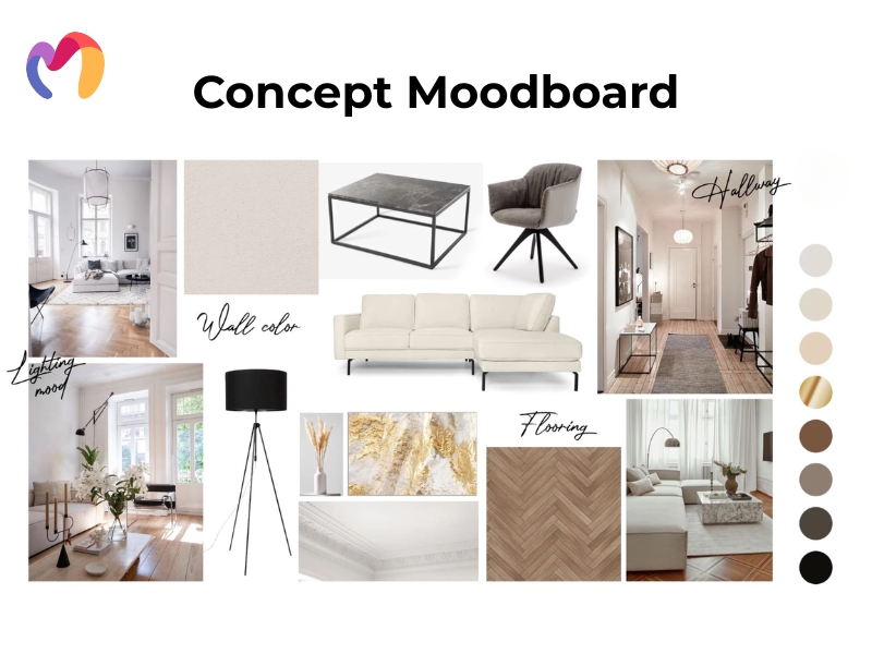
A successful 3D modeling project begins with careful preparation, as gathering references and defining objectives sets a strong foundation and aligns expectations with clients. Concept art guides the creative vision, establishing architectural style, level of realism, chosen materials and lighting conditions that inform all modeling decisions.
Reference materials should cover multiple categories for thorough preparation:
- Primary sources: Images, sketches and drawings directly related to the project
- Secondary details: Additional elements that enhance realism and context
- Technical specifications: Blueprints, measurements, polygon limits and texture requirements
- Inspiration references: Artistic style, mood boards and atmospheric guides
Model sheets and architectural plans provide precise dimensions, supporting spatial accuracy, structural forms and proportional correctness for realistic environments. Defining project scope involves outlining deliverables, technical limits and timelines with measurable milestones, while early client communication documents requirements, confirms expectations and clarifies file formats and budgets. Together, these steps create a shared understanding of the project, guiding the workflow efficiently and producing high-quality, visually accurate 3D models for interior, exterior and architectural design.
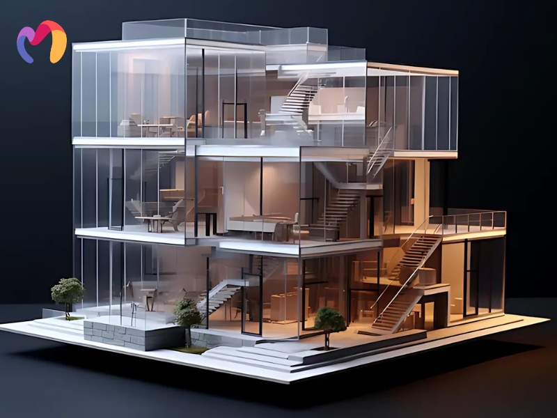
Step 2: Blocking and Basic Shape Creation
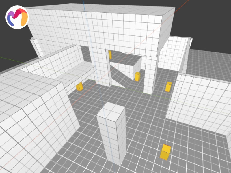
Blocking forms the foundation of 3D modeling, as it establishes the main shapes, proportions and overall silhouette before finer details are added. Primitive shapes provide the basic volumes needed to build complex structures efficiently, including:
- Cubes: For torsos, architectural elements and mechanical parts
- Spheres: For rounded forms or body parts
- Cylinders: For pipes, columns and limbs
- Cones: For pointed features and organic transitions
- Planes: For flat surfaces and background elements
Mass distribution, scale and proportion guide the placement of architectural elements, room dimensions, ceiling heights and key furniture, while blockouts allow designers to test spatial relationships early. Rough models support quick adjustments to layout and functionality, which helps refine the design without committing to specific features prematurely.
Edge loops, support edges and controlled mesh density strengthen the basic forms, giving the model a clear structure and defined contours. A strong silhouette and visual hierarchy emerge from this process, guiding future refinement and ensuring balanced, realistic 3D models for interior, exterior and architectural visualization.
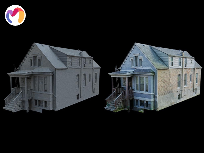
Step 3: Detailed Modeling Techniques
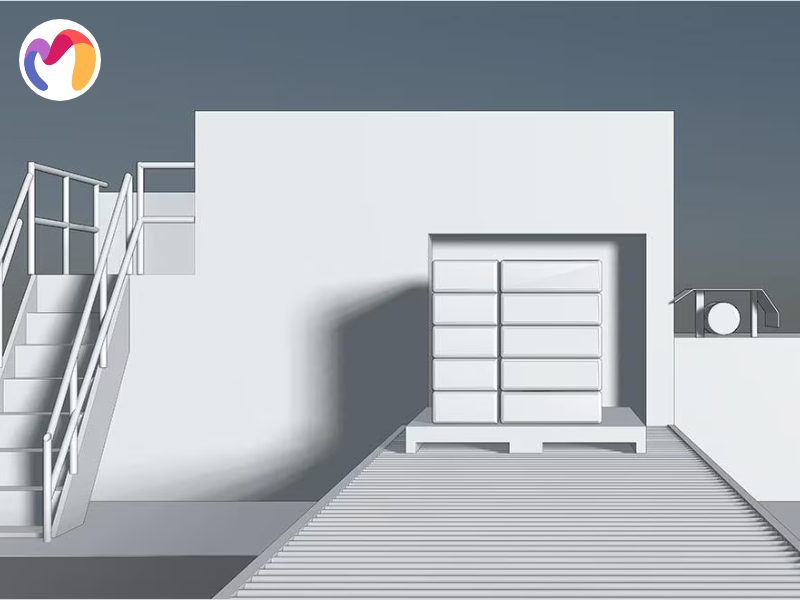
The process starts with low-poly modeling to establish the basic form, as it builds an efficient and optimized foundation for the model. Low-poly meshes focus on simplified geometry, clean edge flow and manageable polygon counts, which preserve flexibility for future adjustments.
Architectural elements, such as walls, roofs, windows and doors, are accurately proportioned and grouped components or interior zones are assessed for balance and spatial relationships. Reference materials, such as blueprints and site plans, guide scaling and alignment, while flat surfaces maintain reduced complexity to allow for fast iteration.
The process then advances to high-poly sculpting to add intricate details, as subdivision and sculpting tools refine surfaces with moldings, carvings, cracks and textures. Non-destructive workflows preserve the core structure, edge alignment and UV mapping, allowing detailed depth without compromising the low-poly base for later texture baking.
Step 4: Texture Mapping and UV Unwrapping
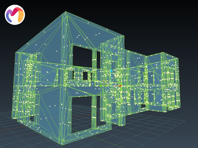
Texture mapping begins with UV unwrapping, as it converts a 3D model’s surface into a 2D layout and allows textures to align accurately. UV shells are grouped by architectural regions such as walls, floors and ceilings and this organization improves clarity and workflow efficiency.
Key UV mapping tasks include:
- Understanding UV coordinates: “U” runs horizontally and “V” vertically, with each 3D face aligning to a 2D section using visible grids to detect misalignment.
- Efficient unwrapping: Planar mapping for flat surfaces, cylindrical for rounded forms, spherical for curved objects and automatic methods for complex meshes.
- UV shell repetition: Duplicate elements, such as tiles, bricks or window frames, to optimize texture use and reduce redundancy.
Texture creation applies maps such as albedo, normal, roughness, metallic and ambient occlusion, following a workflow from base colors to detailed maps for realistic and professional results.
Careful shell placement minimizes seams, maintains consistent texel density and ensures that architectural materials and surface details appear visually accurate and natural.
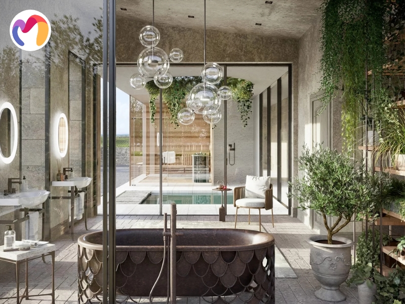
Step 5: Materials and Shading
Materials and shaders determine how 3D models interact with light, controlling surface properties such as reflection, transparency and roughness, which in turn shape the model’s realism or stylistic look. Shading techniques guide visual effects that can be tailored to specific rendering needs and contexts.
Choosing appropriate materials involves considering how surfaces respond to light:
- Game assets: Use optimized shaders to maintain performance.
- Archaeological reconstructions: Apply historically accurate materials.
- 3D printing: Focus on thickness and structural stability.
- Geological models: Layer materials and adjust transparency for depth.
Custom shaders enable precise control over surface interactions, allowing users to manipulate textures and lighting using node-based editors or shader languages like HLSL, while striking a balance between quality and performance. Applying materials systematically includes base textures, detail maps, bump/displacement maps, specular and normal maps and optimization strategies such as consistent resolution, texture atlasing, material instances and adherence to PBR principles, which together produce realistic and visually appealing 3D models.
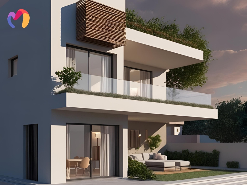
Step 6: Lighting and Rendering
Lighting, rendering, and post-processing determine how 3D models appear, shaping realism, depth, and visual impact. Each stage builds on the previous one to enhance the final image. Proper lighting sets the mood, rendering converts geometry into refined images and post-processing fine-tunes color, contrast and atmospheric effects.
Setting up lighting often begins with the three-point lighting system:
- Key Light: Positioned at an angle to produce strong highlights.
- Fill Light: Reduces harsh shadows for balanced illumination.
- Back Light: Separates subjects from backgrounds, adding depth.
Scenes also employ various light types: directional, point, spot and area, with adjustments to intensity, color temperature, shadows, bounce and falloff. Rendering software such as V-Ray, Arnoldor or Corona simulates real-world light behavior, calculating reflection, refraction, visibility, subsurface scattering and physically based methods that mimic camera settings like exposure, lens effects and depth of field.
Optimization strategies include adjusting sampling rates to balance noise and render time, using render layers for isolated control, applying proxy objects for high-poly assets and selecting resolutions suitable for the intended output. Post-processing refines the final composition through color grading, depth-of-field effects and compositing techniques such as lens flares or fog, producing images that communicate design intent, support client presentations and guide further material and lighting adjustments.
Step 7. Refinement and Quality Assurance
A well-structured quality assurance process is essential for delivering reliable, high-performance 3D models and it guarantees that every asset functions seamlessly across intended platforms while meeting industry standards.
- Reviewing and Testing 3D Models: Evaluate geometry, topology, UV mapping, test animation, rendering and real-time performance to catch issues early and guide refinements.
- Optimizing Performance and Efficiency: Reduce polygon density, simplify meshes, consolidate materials, arrange UV layouts efficiently and implement LODs to maintain smooth performance while preserving visual detail.
- Fixing Common Issues and Errors: Correct face orientation, weld vertices, perform retopology and resolve non-manifold geometry, using validation procedures to ensure production-ready models and minimize rework.
Step 8. Final Delivery and Project Completion
Delivering a project involves more than sending files and it requires that all assets are well-organized, documented and fully optimized for client use. File preparation includes verifying mesh integrity, checking texture and material assignments, confirming correct scale and units, testing animations if applicable and arranging folders systematically for easy access.
- File Preparation: Structured files include accessible 3D assets in native formats (.max, .mb, .blend), exchange formats (.fbx, .obj, .dae), rendered outputs (.jpg, .png, .tiff)and project documentation (.pdf) for multiple uses.
- Quality Checking: Verification ensures mesh integrity, correct material and texture assignments, accurate scale and units, functioning animation playback, proper folder organization and the inclusion of all required assets.
- Documentation: Project documents provide model hierarchy, material and texture specifications, rendering settings, technical constraints, optimization strategies, implementation steps and troubleshooting guidelines to support client integration.
- Feedback Management: Revision tracking maintains logs of modifications, collects structured feedback, organizes version control and supports open communication for efficient updates and potential rollbacks.
| Discover hundreds of free 3D models and elevate your next project — start exploring now! | |||
 |
 |
 |
|
| Decoration 3d model | Pictures 3d model | Books 3d model | Curtain 3d model |
What should be considered when processing the 3D Modeling workflow?
Successfully managing a 3D modeling workflow depends on three practical factors that influence both efficiency and output quality:
- Proper File Organization: Folder structures group files by project and separate them into assemblies, components and types like textures or drawings, which supports collaboration and prevents misplacement. Subfolders store each design version and version control helps teams track revisions and maintain consistency.
- Understanding Software Limitations: Software tools offer different capabilities and file-handling strengths and these differences affect performance with complex models or integrations. Constraints define which tool best fits each stage and familiarity with limits allows smoother task-switching between applications.
- Optimizing for Specific Project Needs: Project goals determine the direction of the modeling workflow and architectural work often requires accuracy for construction compatibility. Parametric modeling supports production demands and early alignment with final output formats improves visualization and integration later in the pipeline.
Conclusion
This guide presents a structured 3d modeling workflow, linking each stage from reference collection and blocking forms to materials, textures and rendering, while handling mesh optimization, UV mapping and scene setup. It helps designers tackle production challenges by breaking the process into clear steps that improve speed, visual quality and spatial accuracy for architectural and interior projects. 3DMaxter’s model library supports each stage with ready-to-use assets in .max, .obj and .fbx formats, combined with quality control, allowing designers to streamline projects and integrate models efficiently for rendering, animation or client presentations.
3DMAXTER LTD
- Email: [email protected]
- Phone: +1 (929) 450-2898
- Address: 95-38 Queens Blvd, Rego Park, NY 11374, USA
3DMAXTER
![]()
![]()
![]()
![]()
![]()
Related Posts
With their diverse designs, dome pendants not only provide functional illumination but also add a touch of personality and elegance to any room. Whatever your preferred style may be, there's a dome pendant to match every taste and complement any interior decor seamlessly.